The qustion how to wire a two way switch can transform how you control lighting in your home, especially in areas like hallways and staircases where multiple control points are essential.
While the concept might initially seem complex, with its common terminals and L1 and L2 terminals used for switch live wires, it’s a straightforward project with proper guidance. Before starting any electrical work, understanding safety protocols and wiring configurations is critical for a safe, effective installation.
Table of Contents
Key Takeaways
Two-way switches allow you to control a single light from two locations. The installation requires proper wire identification, secure connections, and strict adherence to safety protocols. Professional installation is recommended for complex systems to ensure compliance with electrical regulations.
What is a Two Way Switch System?
A two-way switch system differs from a standard light switch by controlling a single light fixture from two separate locations. The system uses special wiring configurations with switch live wires also known as traveller wires connecting both switches, enabling independent control from either location. The setup proves particularly useful in hallways, staircases, or large rooms requiring multiple lighting control points.
Required Tools and Materials
A professional two-way switch installation requires specific tools and materials:
Essential Tools:
- High-quality voltage tester (Category III or IV rated)
- Insulated screwdrivers
- Wire strippers (adjustable gauge)
- Cable cutters
- Circuit testing multimeter
Required Materials:
- Three-core and earth cable (1.5mm² standard)
- Two-core and earth cable (1.5mm² standard)
- Two two-way switches
- Switch mounting boxes
- Wire connectors (appropriate size)
- Electrical tape
- Cable identification sleeve in brown colour.
Safety Precautions
Safety must be your primary concern when working with electrical installations:
- Locate and switch off the correct circuit at the consumer unit
- Use a voltage tester to verify power disconnection
- Wear appropriate insulated gloves
- Use non-conductive tools
- Follow BS 7671 wiring regulations
- Double-check all connections before restoring power
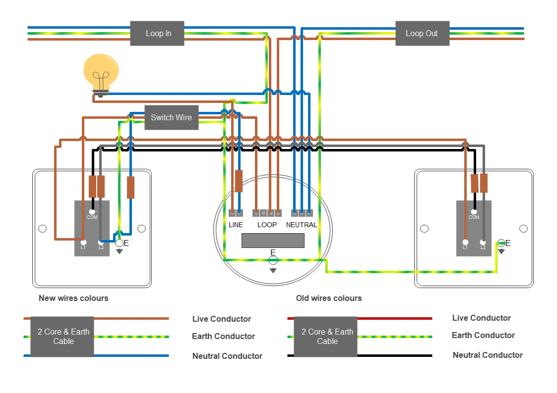
Wire Colour Identification Guide
Modern Wiring Colours:
- Brown: Live conductor
- Blue: Neutral conductor
- Green/Yellow: Earth conductor
- Grey (with brown sleeve): Switch live
- Black (with brown sleeve): Switch live
Legacy Wiring Colours:
- Red: Live conductor
- Black: Neutral conductor
- Green: Earth conductor
- Blue (with brown sleeve): Switch live
- Orange (with brown sleeve): Switch live
Step-by-Step Installation Process
Step 1: Main Supply Connection

- Connect the main supply twin and earth wire from the consumer unit to the light-fitting
- Identify three terminal sets: Line, Loop, Neutral
- Connect brown wire to Loop terminal
- Connect blue wire to Neutral terminal
- Fit earth conductor with green/yellow sleeve to earthing terminal
Step 2: First Switch Connection

- Run twin and earth cable from light fitting to first switch
- At light fitting:
- Connect brown (Live) to Loop terminal
- Connect sleeved blue wire to Line terminal
- At first switch:
- Connect brown wire to L1 terminal
- Connect sleeved blue wire to L2 terminal
- Connect earthing conductor to appropriate terminal
Step 3: Second Switch Connection

- Install three-core and earth cable between switches
- At first switch:
- Connect brown-sleeved grey wire to common terminal
- Connect brown wire to L1
- Connect brown-sleeved black wire to L2
- At second switch:
- Connect brown-sleeved grey wire to common terminal
- Connect brown wire to L1
- Connect brown-sleeved black wire to L2
- Ensure all earth conductors connect to earthing terminals
Testing Procedures
Continuity Testing:
- Set multimeter to continuity mode
- Test between Common and L1/L2 terminals
- Verify connections at both switches
- Check earth continuity
Voltage Testing:
- Restore power safely
- Measure voltage at light fitting
- Test switch operation from both locations
- Document all test results
Troubleshooting Guide
Common Issues:
- Light fails to operate:
- Check power supply connection
- Verify terminal connections
- Test switch continuity
- Single switch operation only:
- Examine traveller wire connections
- Check terminal tightness
- Verify switch mechanism
- Intermittent operation:
- Inspect for loose connections
- Check wire insulation
- Test terminal security
Alternative Wiring Methods
Method 1: Direct Power to First Switch
- Connect live wire to first switch common terminal
- Link L1/L2 terminals between switches
- Connect second switch common to light fitting
Method 2: Parallel Connection
- Connect L1 terminals to live wire
- Connect L2 terminals to light fitting
- Ensure proper earth connections
System Upgrade Guidelines
Converting Single to Two-Way:
- Identify existing circuit configuration
- Install three-core and earth cable
- Connect switches according to chosen method
- Test thoroughly before completion
Final Thoughts
Installing a two-way switch system requires careful attention to detail and strict adherence to safety protocols. While this guide provides comprehensive instructions, always prioritize safety and compliance with local electrical regulations. For complex installations or if you’re uncertain about any aspect, consult a qualified electrician to ensure a safe, reliable result.
Frequently Asked Questions
How Do You Wire a 2-Way Switch?
Connect the power source to the first switch’s common terminal, link both switches with switch live (traveller) wires, and join the second switch’s common to the light fixture. Don’t forget to ground everything properly.
Does It Matter Which Wire Goes Where on a Light Switch?
Yes, it does matter. You’ll need to connect the live wire to the common terminal while traveller wires go to L1 and L2. Incorrect wiring can cause safety hazards or make your switch malfunction.
Why Does My 2-Way Switch Have 3 Wires?
Your 2-way switch has three wires because you’ll need one common wire for power and two traveller wires to connect between switches. This setup lets you control the same light from two different locations.
What Cable Is Needed for a 2-Way Light Switch?
You’ll need a three-core and earth cable for your two-way light switch. It should have three insulated wires (live, neutral, and two travellers) plus an earth wire, typically 1.5mm² for standard lighting circuits.
Related post: